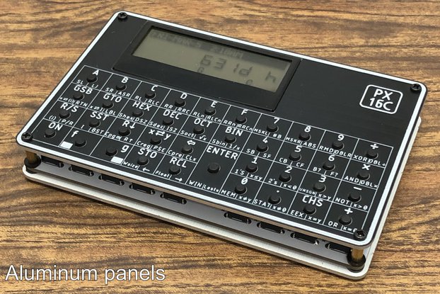
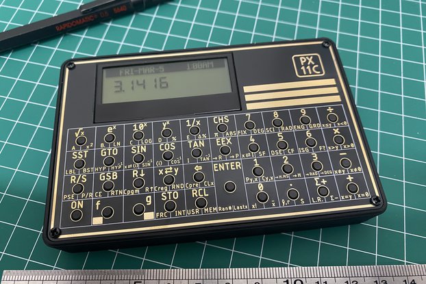
DIY Pocket Calculator (Soldering Kit) with DEC-HEX-BIN Conversion
Designed by Universal-Solder in Canada
Buy with confidence.
Our Tindie Guarantee protects your purchase from fraud. Learn More
The Arduino Pocket Calculator DIY Kit by CANADUINO combines a vintage 10-digit 5×5 LED matrix display with an ATmega328P microcontroller to create a functional educational tool. The kit includes pre-…
Read More…The Arduino Pocket Calculator DIY Kit by CANADUINO combines a vintage 10-digit 5×5 LED matrix display with an ATmega328P microcontroller to create a functional educational tool. The kit includes pre-assembled surface-mount components and requires through-hole component assembly by the customer. Pre-loaded firmware provides immediate functionality, while complete source code enables customization and learning.
3D design file for an enclosure is available for download.
Arithmetic Operations Basic operations: Addition, subtraction, multiplication, division Advanced functions: Square root, reciprocal (1/x) Floating point support with up to 6 decimal places Signed number support (positive and negative values) Operation chaining (sequential calculations without clearing) Error handling for division by zero and mathematical errors
Number System Modes Decimal Mode: Standard base-10 calculations with floating point support Hexadecimal Mode: Base-16 display and input (0-9, A-F) Binary Mode: Base-2 display and input (0-1) Real-time conversion between number systems Hexadecimal letter entry via long-press key detection (500ms threshold)
Display Characteristics 10-digit capacity Right-aligned numerical display Overflow detection and indication Seven adjustable brightness levels (6% to 100%, adjustable in source code) Custom startup message (modifiable in source code)
Technical Specifications Model: ATmega328P-PU Clock: 8MHz internal oscillator Operating voltage: 4.0V - 5.5V Programming interface: ICSP header (pre-installed)
Display
Model: SCD55100A (Osram/Siemens) Configuration: 10 digits, 5×5 LED dot matrix per digit Colors available: Red (SCD55100A), Yellow (SCD55101A), Green (SCD55103A) Interface: 3-wire serial + reset Brightness levels: 7 programmable settings
Input Interface 24-key tactile button matrix Configuration: 6 rows × 4 columns Scanning method: Software matrix scanning with debounce Long-press detection: 500ms threshold for special functions
Power System Power source: 3× AA batteries (not included) Nominal voltage: 4.5V Operating range: 4.0V - 5.5V Power switch: Slide switch included
PCB Specifications Pre-assembled SMD components (1206 package) Through-hole component assembly required ICSP programming header installed
Power Consumption Current draw varies with display brightness setting: Default operation (40% brightness): approximately 60mA Low power mode (20% brightness): approximately 40mA Maximum brightness (100%): approximately 150mA Minimum brightness (6%): approximately 20mA
Battery Life Estimates (2500mAh AA batteries): Continuous operation at 40% brightness: approximately 40 hours Continuous operation at 20% brightness: approximately 60 hours Typical intermittent use: several weeks to months
Components Requiring Assembly ATmega328P-PU microcontroller (pre-programmed) SCD55100A LED display module 24 tactile push buttons Power slide switch 3× AA battery holder with wire leads - watch polarity!! 2 DIP28 IC sockets (optional use)
Available Digital Resources Arduino source code V1.6 with comprehensive comments (download from CANADUINO website) SCD55100A display library (download from CANADUINO website) SCD55100A library documentation (download from CANADUINO website) 3D printer STL file for enclosure (download from CANADUINO website) Schematic diagram
!! Not Included !! 3× AA batteries (alkaline recommended) 3D printed enclosure (available HERE)
Assembly Requirements Skill Level: Beginner to intermediate soldering experience recommended
Assembly Process Solder 24 tactile buttons to PCB Install power switch Install LED display (direct solder or socket) Install microcontroller (direct solder or socket) Attach battery holder wire leads: red to [+] and black to [-] Install batteries and test functionality Optional: Install in 3D printed enclosure
Note on IC Sockets: Two DIP28 sockets are included for component removal convenience. However, direct soldering is recommended for permanent installations. IC sockets can develop contact resistance issues over time, affecting reliability.
Complete calculator logic: Matrix keypad scanning with debounce Long-press detection for hexadecimal letters Display optimization for minimal current consumption Base conversion algorithms Error handling and overflow detection
Arduino source code with educational comments explaining: Keypad matrix scanning implementation State machine architecture Number base conversion algorithms Display multiplexing and optimization Long-press detection logic Memory management strategies
Code Customization Options (examples): Adjust display brightness levels Modify startup message Add mathematical functions Implement additional number bases Customize key mappings Add memory storage functions
3D Printed Enclosure A professional enclosure design is available for download in STL format.
Educational Value / Learning Objectives: Understanding embedded programming concepts Binary, hexadecimal, and decimal number systems Through-hole soldering techniques Matrix keyboard scanning algorithms Display multiplexing and control State machine implementation Firmware development and debugging
Arduino Library for SCD55100A display: We developed an easy to use library that is available for download.
Warranty and Support The provided firmware and source code are offered for educational purposes without warranty. The code may contain errors or bugs. Users are encouraged to review, understand, and modify the code as needed. Software updates and corrections will be made available as issues are identified.
The Arduino Pocket Calculator DIY Kit Includes: 1 x PCB assembly with pre-installed SMD components 1 x ATmega328P-PU (pre-programmed) 1 x SCD55100A LED display 24 x Tactile push buttons 1 x Power slide switch 1 x Battery holder (3× AA) 2 x DIP28 IC sockets 4 x Mounting screws
No country selected, please select your country to see shipping options.
No rates are available for shipping to .
Enter your email address if you'd like to be notified when CANADUINO Arduino-based Pocket Calculator DIY Kit can be shipped to you:
Thanks! We'll let you know when the seller adds shipping rates for your country.
| Shipping Rate | Tracked | Ships From | First Item | Additional Items |
|---|---|---|---|---|
|
:
|
We ship daily from our warehouse in Windsor, Ontario. It might take up to 3 business days to process and ship your order. All shipments are insured and trackable.
Buy with confidence.
Our Tindie Guarantee protects your purchase from fraud. Learn More
$26.90
Free Shipping!
$44.90
Free Shipping!
$11.90
Free Shipping!
$44.90
Free Shipping!
$18.90
Free Shipping!
$15.90
Free Shipping!
$31.80
Free Shipping!
$15.90
Free Shipping!
$54.99
Free Shipping!
$24.20
Free Shipping!
$84.95
Free Shipping!
$69.99
Free Shipping!
By clicking Register, you confirm that you accept our Terms & Conditions
We recognize our top users by making them a Tindarian. Tindarians have access to secret & unreleased features.
We look for the most active & best members of the Tindie community, and invite them to join. There isn't a selection process or form to fill out. The only way to become a Tindarian is by being a nice & active member of the Tindie community!
