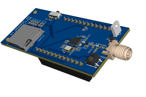
This is ATmel SMART (ARM Cortex M0+) based board with on-board OLED display, micro SD card slot, a successor of SDuino Zero
Designed by microwavemont in Japan
This product is no longer available for sale.
The seller may be offering an improved version or it may be hanging out on the beach, enjoying the retired life.
NOW ULTRA ZERO is made by qualified professional PCB assembly company! QC are full checked Sample Conway's Game of Life available here What is it? This is ATmel SMART (ARM Cortex M0+) based board wit…
Read More…NOW ULTRA ZERO is made by qualified professional PCB assembly company! QC are full checked
Sample Conway's Game of Life available here
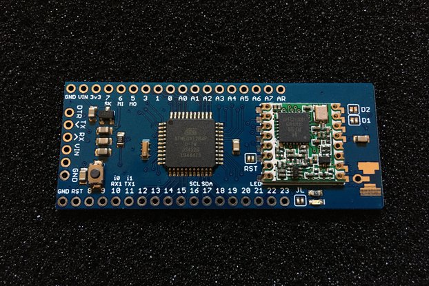
This is ATmel SMART (ARM Cortex M0+) based board with on-board OLED display, micro SD card slot. Main MCU is Atmel SAMD21G18A with 256 kB flash and 32 kB SRAM at speed of 48 MHz, ARM Cortex-M0+ architecture with Arduino IDE programming support.
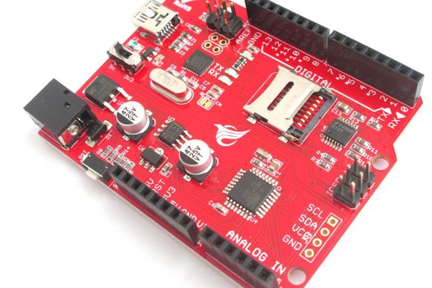
Before I made a SD card sized Arduino Zero compatible, but it lacks for expansion feature, just SD card electrode are all and ends just as a fun. This time I try to make more expandable but self-contained board for solder-less board prototyping and embedded prototype. For selecting MCU, ARM is quite attractive for its rich memory and performance but just using ATmel Studio is a bit hard for beginner. For ease of use I made it as "Arduino Zero compatible" All what you will need is Arduino IDE (of .cc) installation and USB cable plug-in.
This time I made a "ULTRA ZERO" as a successor of SDuino ZERO. This board has OLED display and microSD card on board, and can be easily programmed through Arduino IDE, just selecting Arduino/Genuino Zero (Native USB) at Arduino IDE (of .cc version) tool tab.

As shown in the below schematic, OLED display is connected through I2C with RST D7. SD card is connected via SPI with CS:D10. OLED is SSD1306 based and Adafruit GFX compatible. The voltage can be applied in two ways (1) USB bus power, (2) 5V applying between "5V" and "GN" on board pins, (3) 3.3 V applying between "3.3V" and "GN" on board pins. In any case, all of components including MCU (SAMD21G18A), OLED display, and microSD card are running at 3.3V. Also, all of I/O should be 3.3V logic. (None of pins are 5V tolerant.)

All you will get is (1) Fully assembled and functions are tested (OLED, microSD read/write) main board and (2) pin-header for connection.

For your convenient, Arduino ZERO (of .cc version) boot loader is pre-written for shipment. When you will get, you can program it on Arduino environment. If another environment is preferred, please re-write it with Atmel ICE or some devices.
Following movie is taken by the prototype. Current sales version is in the top picture

/i/73055/products/2017-06-29T09%3A30%3A46.025Z-IMG_2737.jpg?1606306133)