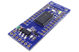
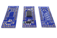
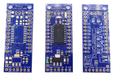
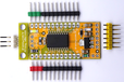
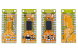
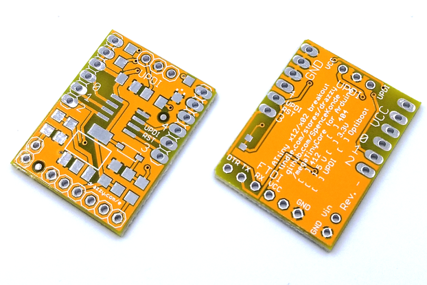
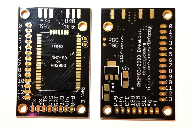
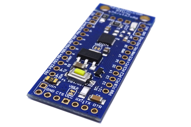
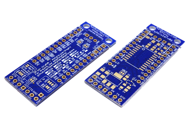
Assembled ATtiny3226, ATtiny3216, or ATtiny 1626 - up to 32k flash 3k ram, 12-bit adc, arduino compatible!
Designed by Azduino by Spence Konde in United States of America
Buy with confidence.
Our Tindie Guarantee protects your purchase from fraud. Learn More
48 pin AVR Dx-series (and EA-series) compatible breakout boards have come back from the board house, will be available as soon as they have been confirmed free of serious issues
Last Chance sale - last chance variant prices cut. While supplies last, buy any "Last Chance" board, and get a free Rev. C bare PCB absolutely free! Convenient, basic development/breakout board for n…
Read More…While supplies last, buy any "Last Chance" board, and get a free Rev. C bare PCB absolutely free!
Over the past half decade Atmel/Microchip has been releasing AVR microcontrollers based on an all new set of peripherals, the megaAVR 0-series and tinyAVR 0/1/2-series, as well as the newer Dx-series. These use the familiar AVR instruction set and open source avr-gcc compiler used with the classic AVR microcontrollers, but with redesigned and more capable on-chip peripherals and highly competitive prices. The AVR instruction set has been given a tuneup but nothing drastic - just timing improvements; with a handful of the most important instructions - mostly those writing to the data space. to SRAM losing a clock cycle (ST, PUSH and CBI/SBI are the ones that matter) which are now all 1 clock instead of 2) The best known of these (among hobbyists, at least) is the ATmega4809, used on the Arduino Uno WiFi Rev.2 and Nano Every. However, there is also an extensive line of tinyAVR parts based on this new architecture - with my megaTinyCore, there is full Arduino IDE support for these, and almost all libraries are either compatible, or have a compatible bundled version included with the core.
The ATtiny 2-series marks the first AVR release with a proper differential ADC (the one on the Dx-series didn't let the voltage go over VREF and had no gain stage, so you couldn't do anythign with it that you couldn't do with 2 simultaneously triggered normal ADCs. Which was entirely possible to rig up on the 1-series, actually...). The top-end 20-pin part of the 2-series is the ATtiny3226, now available (well, it's on backorder like every other part these days, but we've got a fair number), as well as some left over ATtiny 1626's (the 16k version). They appeared on the market first, followed by the smaller versions, and finally by the full 32k ones. The ATtiny3216 meanwhile is the top-end 20-pin tinyAVR 1-series device, with 3 analog comparators, an 8-bit dac, a very unusual dual ADC, and the high speed timer TCD0.
These breakout boards come equipped with your choice of 3.3v or 5v regulator (LDL1117) so that it can be supplied with an external supply (minimum dropout as low as 0.35v!) using the two pins in the lower left corner, an LED (on PA7, Arduino pin 3), and a UPDI programming header (with the ~4.7~ 470 resistor on the board, which can be bypassed with the RBP solder bridge jumper on the back). There is a 1x6 pin "FTDI"-style serial header on the bottom edge of the board. One of the exciting features on 20 and 24-pin 2-series is an optional alternate reset pin! You can use PB4 as reset now.
That means that 2-series boards are made with the autoreset circuit parts installed, and the are shipped with them connected to PB4. This can be disconnected by clearing the solder bridge on the underside of the board.
All pins are broken out, and there are 3 Vcc and 3 Gnd pins available, plus the ones on the UPDI and Serial headers so even if you're not using breadboard, you can still easily connect power and ground for multiple external devices.
Board dimensions are 1.4" x 0.85" with the rows of pins 0.7" center to center for the Rev. B. Rev. C boards (with the darker solder mask for more readable) are 0.75" wide, with the rows of pins 0.6" center to center, so you can use them with wide DIP sockets should you wish to.
This is available as a bare board (supporting all the x26, x16 and x06 parts) here. Want to make lots of them? Buy out our inventory of Rev. B boards, get our own stainless steel stencil (a $25 value) FREE!
The new (march 2021) ATtiny1626, a member of the tinyAVR 2-series is now available. As expected, the 2-series is very nearly 100% pin compatible. (code that uses the event system will need modifications - though they will tend to make code simpler - the 0/1-series event system was a bit of a mess; the 2-series has a normal event system identical to what the top-end AVR Dx-series parts have).
As of January 2022, we are now selling the latest version of our breakout board, the new Rev. C, with a 3226 mounted on it! The 3226 is identical to the 1626 - except that it has 32k of flash and 3k of ram, instead of 16k and 2k. The Rev. C boards boast improved silkscreen, more flexible solder bridge jumper options, and pads to add an external clock in 3225 package and it's decoupling cap if you happen to need one - all in a narrower form factor (same width as a nano - or a wide DIP socket.
analogReadEnh(pin,17);
("enhanced analog read of 'pin' to 17 bits of resolution") - or if you wanted that to be a differential reading? analogReadDiff(positive_pin,negative_pin,17);
You wanted to amplify that by 16x using the PGA too? `analogReadDiff(positive_pin,negative_pin,17,16); - there is a detailed reference for the exposed functions surrounding the ADC included with the megaTinyCore readme Of course, analogRead(pin) will still by default give you a 10-bit reading, though you can, as usual, switching between the resolutions supported in hardware for a single conversion (8 or 12 - the 10 is a compatibility shim that takes a 12 bit reading and drops the two LSB). I make no claims as to how many of those extra bits you get from oversampling and decimation are noise vs signal - it doesn't take much to throw off a 17-bit ADC measurement, and will likely need to take extra power supply filtering measures to make the most of the new ADC. However, even without that, it is significantly more capable than the 1-series ADCThe ATtiny1606 is the top-end 0-series part in a 20-pin package. The 0-series is intended for low cost applications, and cuts a few features. For hobbyists and one-off projects, these are not a compelling choice, and unsurprisingly, they did not sell well. The 0-series essentially combines the worst parts of the 1-series and 2-series, and found a way to make it worse by shedding ram, a timer, external voltage reference, and half of the 1-series' already somewhat strange event system. Compared to the 3216, it has: 16k flash insted of 32k, 1k SRAM instead of 2k, a single 10-bit ADC, only 1 type B timer (so Servo and Tone can't be used at the same time), no DAC, no Type D timer, 1 analog comparator, no external analog reference, only 3 event channels, none of which can use the RTC PIT as generator. (can you see why these weren't hot sellers? Apparently they still sell well enough that they're backordered from the manufacturer though....)
In some of the pictures shown above, the boards are shown with pin header (not included) attached. We recommend:
We offer an optional colored pinheader kit containing: 1x3 red and green - for the Vcc and Gnd pins 2 pcs 1x6 - for the I/O pins 1x6 yellow, 90 degree angle - for the serial adapter 1x3 white, 90 degree angle - for connecting a UPDI programmer These are all cut using a precision slicer, so they fit up against eachother easily (you can't break or cut them with plain wire cutters if you want it to look good.)
There are two approaches to programming these parts:
Unlike "classic" AVR microcontrollers, these new parts are programmed via a "UPDI" single wire interface instead of the SPI-based ICSP protocol. You can easily make a UPDI programmer from (almost) any serial adapter with a schottky diode or 4.7k resistor, (I found that the diode worked far better - some people disagree and the matter has not yet been fully explained). As of the most recent releases of my megaTinyCore which improved performance using this method (it now leaves jtag2updi and Microchip's official programmers in the dust), this is what we recommend; see the instructions here;
The 2.4.0 release has further improved compatibility with a wide range of serial adapters by ensuring that the non-TURBO mode (turbo mode being "go faster at all costs, including buying inexpensive serial adapters (Blue DeekRobot FT232RL and black CH340G with voltage switch are both great adapters for this); the DeekRobot RT232RL boards even have an A that don't suffer from implicit latency) does not implicitly use the USB latency to give the chip a chance to perform the page write, making it work with (almost) all adapters. The performance will fixed back up in a future version to get rid of most of the performance penalty (up to 1 second per upload).
Make UPDI programmer from either a serial adapter and a diode, or a Nano/ProMini/Uno
The order of the pins on the UPDI header is UPDI-Gnd-Vcc - this means that if the programmer is connected backwards, the board will not be damaged. The 470 ohm resistor is compatible with all three of the most plausible options: SerialUPDI ( resistor is on the breakout board; you do not need to (and should not) use another one.
A typical development configuration might have the board connected to a serial port via the 6-pin serial header for serial debug, and to the UPDI programmer via the 3-pin header for uploading new code (as shown in the pictures). This is generally how we use it, and is what we recommend.
The Optiboot bootloader is supported for all parts; this works with an external serial adapter (like the 6-pin ones used for the Arduino Pro Mini). Optiboot takes up 512b of flash for the bootloader. In addition to obliviating the need for a UPDI programmer to upload sketches (though note that the same serial adapter could also be used as a UPDI programmer, Optiboot allows you to use the same port for upload and serial monitor like a normal Arduino board.
There are two general approaches to using Optiboot on these parts and a third, much better way on 2-series parts:
Without auto-reset, UPDI enabled. On all boards that do not support auto-reset, and on boards that do if this option is selected, the UPDI/Reset pin will be left as UPDI, and the board can be freely reprogrammed via UPDI. The version of the bootloader installed will be active for 8 seconds after power on, or after a WDT or software reset. So for example, to upload, you would verify sketch, unplug, plug back in, and then upload - or alternatively, you could adapt your sketch to trigger a software reset. UPDI programming will still be possible. Note that for these boards, you must use UPDI to "burn bootloader" with the non-optiboot board definition selected if you want to switch back to uploading sketches via UPDI
With auto-reset - using alternate reset pin (2-series only) or by sacrificing UPDI programming (0/1-series). This is recommended if you want to use Optiboot with the 2-series. We do not recommend using this with 1-series parts, as it precludes further UPDI programmer without an HV UPDI programmer which is still somewhat exotic.
Another approach is to upload sketches which all have a means of triggering a "software reset" from within the sketch, either from a pin interrupt (the existing autoreset parts could be wired to this pin). With other trigger mechanisms, this could be used in more advanced deployments, such as a device at the far end of a serial line, which resets in response to a specific command0). These schemes allow one to use the bootloader without powercycling the board while also permitting use of UPDI programming - however because they depend on the sketch, they are inherently more "brittle", and that UPDI programming option may become necessary to revive boards during development - in the event of bugs in the application. This method is beyond the scope of this product listing.
If purchased without the bootloader installed, if you later decide that you want it, you may install it using a UPDI by doing burn bootloader (if using autoreset and UPDI pin set as reset, the jumper on the back must be closed after bootloading); this pre-bootloading service is intended only as a convenience.
Boards with optiboot preinstalled are bootloaded at the time the order is received. All boards are set to 20-MHz derived clock speeds unless 16 MHz is requested, 4.2 sampled BOD, 3.3v boards are set to 10MHz (will also run at 5MHz) 2.6v sampled BOD. No-regulator boards are set to 20MHz/10MHz/5MHz, with BOD disabled to minimize idle power consumption. Because these are bootloaded on-demand, (and the UPDI pin is configured to act as a reset pin if you choose autoreset for a ATtint3216 or 1606 you will not be able to reprogram the fuses without an HV UPDI programmer; thus, if you have different requirements (eg, 16MHz base clock to allow 16MHz/8MHz/4MHz speeds, or different BOD settings), this can be done, just list what you want in order comments.
More information on Optiboot and the tinyAVR 0/1/2-series parts is available in the megaTinyCore documentation.
The linear regulators offered can provide a regulated operating voltage provided Vin in at least 1.3v (ZLDO1117) higher than the operating voltage. These regulators are appropriate when your current requirements are relatively low, and you have access to a power supply with a voltage higher than the operating voltage (max 18v input) - maximum power dissipation, however, is only ~ 1.2W without adding heatsinks, (that is to say (Vin - Vout)*(current) < 1.2W)
so the practical maximum current is much lower.
Example calculations of maximum current when using the regulator:
Vin=12v, Vout=5v. Vin-Vout=7V. 7V*I < 1.2W -> I < 1.2W/7V -> I < 170mA
Vin=7v, Vout=5v. Vin-Vout=2V. 2V*I < 1.2W -> I < 1.2W/2V -> I < 600mA
Only the Vin pin goes through the regulator - all other Vcc pins (including the UPDI and FTDI headers) are connected directly to the Vcc rail - so if you have a 3.3v regulator, but connect a 5v serial adapter's 5v line to the board, the board will be running at 5v (this will not harm the board itself, as long as the voltage does not exceed 5.5v - but if you have 3.3V devices connected to it, those may be harmed, so if you have any of those connected, you must use a 3.3v serial adapter or power some other way, and not connect the 5v pin of the serial adapter (the data lines are fine, as serial adapters almost universally have a 1k - 2.2k resistor in series with the TX line, while the RX line is only weakly pulled up and can be handled by the protection diodes which will limit the current to a non-dangerous level, or disconnect the 3.3v devices from the board before connecting the 5v to the board's Vcc), whereas if you supply 5v to the Vin pin, the board will be running at 3.3v.
However - a regulator has a quiescent current that it draws to power itself (0.25mA~0.5mA for these regulators). Hence, if you are running on batteries and using power saving techniques, you want to avoid having a regulator on the board if possible. For example, if running off a LiPo/LiIon battery at 3.7~4.2v, you could set it to run at 10MHz, and use no regulator - approximate power use with a regulator (whether or not you power through the regulator or connect power direct to Vcc), the sleep mode power down current will be ~0.25mA (almost all from the regulator), whereas without the regulator, current in sleep mode power down will be ~0.1uA (0.0001mA) at room temperature - that is, for a project where the chip will spend most of it's time in sleep mode power down, the battery life may be 2,500 times longer without the regulator.
If powering from batteries w/out a regulator, you need to be careful not to connect external power directly to Vcc (including from a serial adapter or UPDI programmer) while the battery is connected.
On boards where there is no regulator, the PTC fuse is still present (in series with Vin), and the regulator is bypassed by a 0-ohm resistor, so you can still use the Vin pin power the board to get the benefit of overcurrent protection. See picture 3 for an example of what the "no regulator" looks like.
We can build these with 1.8, or 2.5V regulators in addition to the usual 3.3V, 5V, or bypassed regulator (or it can be left bare if you have some special regulators you want to use for an exotic voltage or ultra low quiescent current and it's compatible with the 1117-SOT223 footprint). Message me to discuss - pricing depends on quantity and delivery time requirements (if you want a full minipanel of 10 PCBs, great - if not hopefully there's some other option we normally stock running low to dedicate the rest of the panel to. These days most of these parts are backordered (the Great 2020's Chip Shortage), however we are well stocked to meet demand or assemble special orders, with: 50x ATtiny3226F (125C) 45x ATtiny3216F (125C)
Tuning can be performed if required (for the (tuned) clock speed options, which include some exotic, yet in-spec clocks, and some overclocked frequencies.
Early versions of this board used a 4.7k resistor. This is an excessive value, and is only compatible with jtag2updi programmers with a series resistor not more than 1k at absolute maximum. This was pointed out to me before SerialUPDI existed, and since then (spring 2020) I've been shipping boards with the correct 470 ohm resistor.
No country selected, please select your country to see shipping options.
No rates are available for shipping to .
Enter your email address if you'd like to be notified when ATtiny3226/3216/1606 dev board, Arduino compatible can be shipped to you:
Thanks! We'll let you know when the seller adds shipping rates for your country.
Shipping Rate | Tracked | Ships From | First Item | Additional Items |
---|---|---|---|---|
:
|
International orders have been suffering long delays due to COVID-19 - please check your country at https://about.usps.com/newsroom/service-alerts/international/ and make sure that I can ship to you, and that you are okay with any delays. There may be additional information available from your national postal service. Some customers have reported packages being delayed in transit by over a month. We cannot offer any sort of guarantees regarding international shipments at this time; we apologize for the inconvenience, and are looking into shipping internationally through UPS.
Please be sure that the address given to Tindie is accurate, and includes your street name and number - company name is only required if shipping to a commercial address. International orders require a valid phone number.
Domestic packages that go more than 1 week without a tracking update will be presumed lost in the mail and refunded or reshipped as buyer prefers. Any international packages can be delayed in customs without warning for 2 weeks or more. After 1 month without a tracking event (2 months to South and Central America - insane delays in those nations are commonplace), we will reship or refund a missing order (as you prefer). COVID-19 update: Some countries have stopped processing incoming international mail entirely -we will cancel orders to countries which we know are not processing international mail at all. This may also cause longer than usual shipping times - we are not responsible for such delays.
We do not open inquiries through the postal service - experience has shown this to be futile.
We ship all orders via USPS. UPS will be added as an option in the near future, I hope. We do all shipping through Stamps.com, and they offer me UPS, but all addresses are rejected as invalid, and I have emailed support numerous times and have had zero response. So at present, we cannot entertain requests to ship through other carriers.
Product: (5.00)
Documentation: (4.75)
Shipping: (4.75)
Communication: (5.00)
Hyeon Sik | March 15, 2021
Willem | Oct. 31, 2020
Timothy | June 6, 2020
David | March 11, 2020
Buy with confidence.
Our Tindie Guarantee protects your purchase from fraud. Learn More
somerville, MA, United States of America
Ships from United States of America.
117 Reviews | 2,220 Orders
$3.75
Free Shipping!
$1.70
Free Shipping!
$13.00
Free Shipping!
$5.00
Free Shipping!
$5.50
Free Shipping!
$37.00
Free Shipping!
$3.00
Free Shipping!
$3.75
Free Shipping!
$7.95
Free Shipping!
$12.50
Free Shipping!
$9.95
Free Shipping!
$15.00
Free Shipping!
By clicking Register, you confirm that you accept our Terms & Conditions
We recognize our top users by making them a Tindarian. Tindarians have access to secret & unreleased features.
We look for the most active & best members of the Tindie community, and invite them to join. There isn't a selection process or form to fill out. The only way to become a Tindarian is by being a nice & active member of the Tindie community!