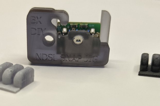
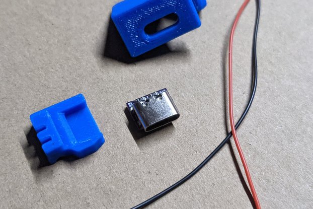
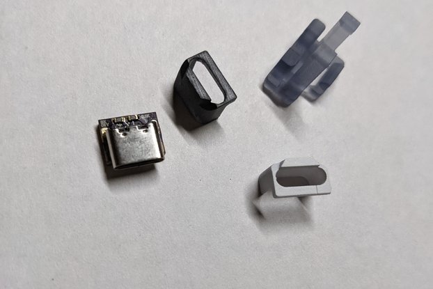
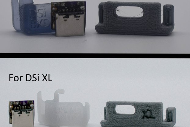
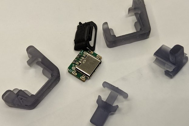
A parts kit to add USB-C charging to the Vita 2000, supports USBC to USBC charging
Designed by BronxDIY in United States of America
Buy with confidence.
Our Tindie Guarantee protects your purchase from fraud. Learn More
About this mod: This is a PCB kit to add a USB-C port to the Vita-2000, this usbc port supports usbc to usbc charging as well as usb A to usb C charging. It comes with two 5.1k Ohm resistors to n…
Read More…About this mod: This is a PCB kit to add a USB-C port to the Vita-2000, this usbc port supports usbc to usbc charging as well as usb A to usb C charging. It comes with two 5.1k Ohm resistors to negotiate 5 volt charging with any usbc charger (you don’t have to worry about your charger having too much power/voltage). This kit comes with a bezel to cover the gaps between the case and the USBC port as well as a resin jig for positioning the USBC port on the motherboard.
Mod Difficulty: 8/10, soldering the flex pcb is a tad difficult and soldering directly to the microusb pins is even harder
Sanding/fitting:
Take the ‘pill’ shaped cutting jig from the kit do step 1 from Dissassembly/installation and then take two of the black screws from the outside case you set aside. Screw the jig onto the case (on the outside with the peg closest to the back of the case).
Use the jig to cut and file the case to widen the charge port hole to accept the usbc port from the pcb. You can use the pcb to double check that the hole is wide enough.
Remove the jig and debur any edges that need it.
Take the black cage that sits on top of the motherboard and snip off the part that sits above the charge port area.
Disassembly/installation:
Find a good video of the disassembly of the vita 2000 and follow that until you remove the motherboard from the system.
Remove and set aside the front and rear cameras.
(Preferred) 3. Place the motherboard on a hot plate set to 150 Celsius let it sit for 30 seconds. Add flux and low temp solder to the pins and joints of the old charging port.
(Preferred) 4. Use a hot air station (I use 300-330 celsius at 80-99% speed) to heat up the old charging port for around 30 seconds or until the solder becomes molten then remove the old charging port.
Use your soldering iron to heat up the joints and pins of the old charging port cycling between them and then wiggle the port off while the solder is molten. This method is difficult and time consuming, do it carefully and slowly.
(While on the hot plate if using a hot plate) Use your soldering iron and soldering braid to carefully wick the pin and joint pads of the old charging port, do it slowly and carefully as to not damage the pins or knock off components. Do this to both sides.
(Optional) 6. Grab the flex pcb from the kit make sure the text portion is facing up and carefully line up the flex pcb to the pins on the motherboard. Tack down the top right pad with your soldering iron then while centering the flex pcb solder the outer and center pads. Use your multimeter to make sure you have continuity between the ground test points on the flex pcb and the motherboard then do the same for the 5v pin and the d+ and d- pins. Use the multimeter to make sure you do not have continuity between 5v and ground or any other pins (5v, d+,d-).
IMPORTANT STEP 8. Take the polyimide half circle stickers from the kit, place two on the pcb kit to cover all the tiny pins coming from the rear of the USBC board. Then take the other pair of stickers and turn the motherboard over to the side with an exposed copper B on it. Use the second pair of stickers to cover the pads on the top of the cavity (two through hole pads). This will keep the pins from being shorted to ground.
Place the pcb from the kit into the jig, slip the jig onto the motherboard and make sure you press it on the side afterward to make sure everything is fully in place. Add flux to the sides of the pcb shield and the pads on the motherboard sides near it, bridge flux between the shield of the pcb and the pads of the motherboard (refer to pictures).
Flip the motherboard and remove the jig by pulling up the center tab and pushing the jig off. Add flux and solder both sides of the pcb to the motherboard.
Use the wires from the kit or your own to wire the 5v, d+, d- pins on the kit pcb to the motherboard (use the breakout points on the flex pcb if used). Double check for continuity and shorts with your multimeter (like Step 6).
Do a final continuity check then reassemble the vita-2000 you’re done.
REQUIRED BUT NOT INCLUDED TOOLS: 1. Soldering Iron 2. Flux 3. Solder 4. Phillips screwdriver (size 0 covers most devices) 5. Multimeter with continuity mode 6. Files and/or rotary tool 7. Flush Cutters 8.Tweezers
(highly) RECOMMENDED BUT NOT INCLUDED TOOLS: 1. Hot air station 2. Hot plate
INCLUDED: 1. USB-C PCB 2. Resin Installation Jig 3. Flex breakout pcb 4. Wires 5. Polyimide stickers
No country selected, please select your country to see shipping options.
No rates are available for shipping to .
Enter your email address if you'd like to be notified when Vita-2000 USB-C Replacement port w/ jig can be shipped to you:
Thanks! We'll let you know when the seller adds shipping rates for your country.
Shipping Rate | Tracked | Ships From | First Item | Additional Items |
---|---|---|---|---|
:
|
Buy with confidence.
Our Tindie Guarantee protects your purchase from fraud. Learn More
$12.00
Free Shipping!
$12.00
Free Shipping!
$12.00
Free Shipping!
$12.00
Free Shipping!
$12.00
Free Shipping!
$12.00
Free Shipping!
$12.00
Free Shipping!
$12.00
Free Shipping!
By clicking Register, you confirm that you accept our Terms & Conditions
We recognize our top users by making them a Tindarian. Tindarians have access to secret & unreleased features.
We look for the most active & best members of the Tindie community, and invite them to join. There isn't a selection process or form to fill out. The only way to become a Tindarian is by being a nice & active member of the Tindie community!