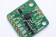
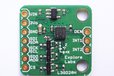
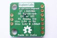
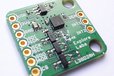
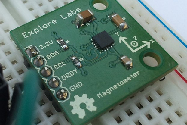
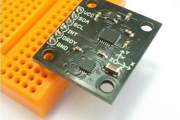
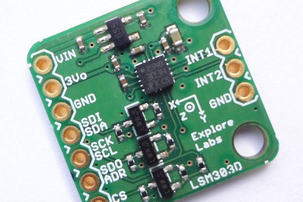
Explore Labs Triple-Axis Gyroscope L3GD20H Breakout Board 5V Ready with Voltage Regulator works with I2C and SPI interface.
Designed by Explore Labs in IndiaNo shipping info available.
Set destination country to see options
Shipping to starts at
Free shipping is available to !
Ships from
This item does not ship to .
More Info
Sign up to get notified when this product is back in stock!
This breakout board is based on ST L3GD20H three-axis gyroscope, which measures the angular rates of rotation about the roll (X), pitch (Y), and yaw (Z) axes. Angular velocity measurements with a con…
Read More…This breakout board is based on ST L3GD20H three-axis gyroscope, which measures the angular rates of rotation about the roll (X), pitch (Y), and yaw (Z) axes. Angular velocity measurements with a configurable range of ±245°/s, ±500°/s, or ±2000°/s can be read through a digital I2C or SPI interface.
The carrier board includes a low-dropout linear voltage regulator that provides the 3.3 V required by the L3GD20H, which allows the sensor to be powered from 2.5 V to 5.5 V. The regulator output is available on the 3Vo pin which can supply approx. 150 mA to external devices.
The breakout board also includes a circuit that shifts the two I2C lines or all four SPI lines (clock, data-in/out and chip select) to the same logic voltage level as the supplied VIN, making it simple to interface the board with 5V systems; and the board’s 0.1″ pin spacing makes it easy to use with standard solderless breadboards and 0.1″ perfboards. The board ships fully populated with its SMD components, including the L3GD20H, as shown in the product picture.
Features of Explore Labs 3D Gyroscope L3GD20H Breakout Board:
Features of L3GD20H sensor IC:
Specifications:
Applications:
Output Format: Provides individual readings for each axis in degrees per decond (dps). These readings may be used separately or together with an Accelerometer for 3D calculations like calculating euler angles (roll, pitch, yaw) and other complex orientation calculationsfor Inertial Measurement Units (IMU).
Pinout Table
Pin | 5V Safe? | Function |
---|---|---|
VIN | Yes | Input Voltage Pin: 2.5V to 5.0V (depending on Master device being used as mentioned in later connection sections and tables below). |
3Vo | Not Applicable | This is the output pin of the onboard 3.3V Voltage Regulator. It provides a clean and regulated 3.3V output to the sensor IC. It can also be used by the user to provide power to external devices or sensors. Maximum current that can be sourced easily would be approximately 125mA to 150mA after leaving some room for the on board sensor IC. |
GND | Not Applicable | Ground Connection. Connect this pin to the master device's ground pin or to any externally powered devices from onboard regulator. |
SDI/SDA | Yes. Bidirectional MOSFET with 4K7 pull-ups. | This pin has dual functions - Serial Data Input (for SPI) or Serial Data (for I2C). In case of SPI, it can also be called as Master Out Slave In (MOSI). |
SCK/SCL | Yes. Bidirectional MOSFET with 4K7 pull-ups. | This pin is the serial clock input pin. It is common for both SPI and I2C interfaces. |
SDO/ADR | Yes. Only a 4K7 pull-up resistor needed as this is an output pin. | This pin has dual functions - Serial Data Output (for SPI) or Address Select (for I2C). In case of SPI, it can also be called as Master In Slave Out (MOSI). In case of I2C, this pin may be pulled LOW or grounded for selecting an alternate address to avoid address conflicts with similar I2C devices. The change will have to be updated in code as well. Leave unconnected if no change in address required for I2C. |
CS | Yes. Bidirectional MOSFET with 4K7 pull-ups. | Chip Select or Slave Select pin. By default, it is pulled HIGH using an onboard 4K7 pull-up resistor. This sets the default mode of communication for the sensor IC as I2C. For SPI, this pin acts as the chip select pin to communicate with an SPI master device. Leave unconnected when using I2C. |
DEN | No. Take proper care when interfacing with devices that have higher voltage levels. This pin is not 5V tolerant! | Data Enable input pin. The L3GD20H allows external trigger level recognition through enabling the EXTRen (bit7) and LVLen (bit6) bits in CTRL2 (21h) register and the IMPen (bit3) bit of CTRL4 register. Three different modes can be used: level-sensitive, pulse-sensitive and edge-sensitive trigger. More detailed explanation can be found in Section 3.5 of ST Application Note AN4506. |
INT1 | No. | Interrupt output pin. The L3GD20H interrupt signal can be configured in a very flexible way allowing to recognize independent rotations of the X, Y and Z-axis. That signal can be driven to the INT1 pin. The device may be configured to generate interrupt signals by detecting an independent wake-up event. Thresholds and timing of the interrupt generator are programmable by the end user on the fly. More detailed explanation can be found in Section 5 of ST Application Note AN4506. |
INT2 | No. | Second Interrupt output pin. This pin is dedicated to DRDY and FIFO interrupts. DRDY Interrupt: The device may be configured to have one HW signal to determine when a new set of measurement data is available for reading. This signal is represented by the XYZDA bit of the STATUS register. The signal can be driven to the DRDY/INT2 pin. FIFO Interrupt: The device may be configured to generate an interrupt on FIFO Threshold, FIFO Overrun or FIFO Empty event. For more details, refer to above application note from ST. More detailed explanation can be found in Section 3.3 and Section 5.1 of ST Application Note AN4506. |
Connections with various development boards are explained below:
The carrier board supports both I2C as well as SPI method of communication with a host microcontroller. The communication mode is selected by pulling the CS pin HIGH or LOW. By default, the CS pin is pulled HIGH through a 4.7 kΩ resistor on the board. This makes I2C communication the default method to talk to this carrier board.
I2C Communication: By default, I2C communication is implemented. The Explore Labs 3D Gyroscope L3GD20H Breakout Board can be configured and its angular velocity readings can be queried through the I2C bus. Level shifters on the I2C clock (SCL) and data (SDA) lines enable I2C communication with microcontrollers operating at the same voltage as VIN (2.5V to 5V). A detailed explanation of the I2C interface on the L3GD20H can be found in its datasheet[1] and more detailed information about I2C Protocol in general can be found in NXP’s I2C-bus specification manual.
I2C Address: In I2C mode, the gyro’s 7-bit slave address has its least significant bit (LSb) determined by the voltage on the SDO/ADR pin. The carrier board pulls SDO/ADR HIGH through a 4.7 kΩ resistor, making the LSb 1 and setting the slave address to 1101011b (0x6B). This is the default device address in I2C mode (same address as the previous generation L3GD20). If SDO/ADR pin is connected to ground, LSb value is ‘0’ which changes the device address to 1101010b (0x6A). This solution permits to connect and address two different gyroscopes to the same I2C bus.
Connecting Explore Labs 3D Gyroscope L3GD20H Breakout Board using I2C (Inter Integrated Circuit) Interface
L3GD20H | Arduino Uno | Arduino Mega | Arduino Leonardo | Arduino Due | Genuino Zero | Genuino 101 | Arduino MKR1000 | Raspberry Pi | BeagleBone Black |
---|---|---|---|---|---|---|---|---|---|
VIN | 5V | 5V | 5V | 3.3V | 3.3V | VCC (3.3V) | 3.3V | 3.3V | 3.3V |
GND | GND | GND | GND | GND | GND | GND | GND | GND | GND |
SDI/SDA | A4 or SDA | Pin 20 (SDA) | Pin 2 (SDA) | Pin 20 (SDA) | SDA | SDA | Pin 12 (SDA) | Pin 3 (SDA1) or GPIO2 | Pin 20 (I2C2_SDA) |
SCK/SCL | A5 or SCL | Pin 21 (SCL) | Pin 3 (SCL) | Pin 21 (SCL) | SCL | SCL | Pin 11 (SCL) | Pin 5 (SCL1) or GPIO3 | Pin 19 (I2C2_SCL) |
Arduino Uno with I2C (Inter Integrated Circuit) Interface
Raspberry Pi (all models) with I2C (Inter Integrated Circuit) Interface
BeagleBone Black with I2C (Inter Integrated Circuit) Interface
SPI Communication: To use the L3GD20H in SPI mode, CS pin must be driven low (connected to GND). A minimum of four logic connections are used viz., SDI, SCK, SDO and CS. These should be connected to an SPI bus operating at the same logic level as VIN. The SPI interface operates in 4-wire mode by default, with SDI and SDO on separate pins. In the default 4-wire mode, the sensor transmits data to the SPI master on a dedicated data out (SDO) line. If the SPI interface is configured to use 3-wire mode instead, the SDI line doubles as SDO and is driven by the L3GD20H when it transmits data to the master. A detailed explanation of the SPI interface on the L3GD20H can be found in its datasheet.
Connecting Explore Labs 3D Gyroscope L3GD20H Breakout Board using Serial Peripheral Interface (SPI)
L3GD20H | Arduino Uno | Arduino Mega | Arduino Leonardo | Arduino Due | Genuino Zero | Genuino 101 | Arduino MKR1000 | Raspberry Pi | BeagleBone Black |
---|---|---|---|---|---|---|---|---|---|
VIN | 5V | 5V | 5V | 3.3V | 3.3V | VCC (3.3V) | 3.3V | 3.3V | 3.3V |
GND | GND | GND | GND | GND | GND | GND | GND | GND | GND |
SDI/SDA | Pin 11 or MOSI | Pin 51 | Pin 4 (ICSP) | Pin 4 (ICSP) | Pin 4 (ICSP) | Pin 11 (MOSI) | Pin 8 (MOSI) | Pin 19 (MOSI) or GPIO10 | Pin 21 (SPI0_D0) |
SCK/SCL | Pin 13 or SCK | Pin 52 | Pin 3 (ICSP) | Pin 3 (ICSP) | Pin 3 (ICSP) | Pin 13 | Pin 9 | Pin 23 (SCLK) or GPIO11 | Pin 22 (SPI0_SCLK) |
SDO/ADR | Pin 12 or MISO | Pin 50 | Pin 1 (ICSP) | Pin 1 (ICSP) | Pin 1 (ICSP) | Pin 12 (MISO) | Pin 10 (MISO) | Pin 21 (MISO) or GPIO9 | Pin 18 (SPI0_D1) |
CS | Pin 10 or SS | Pin 53 | Any IO | Any IO | Any IO | Pin 10 | Any IO | Pin 24 (CE0_N) or GPIO8 | Pin 17 (SPI0_CS0) |
Arduino Uno with Serial Peripheral Interface (SPI)
Raspberry Pi (all models) with Serial Peripheral Interface (SPI)
BeagleBone Black with Serial Peripheral Interface (SPI)
Working Principle: It includes a sensing element and an IC interface able to provide the measured angular rate to the external world through digital interface (I2C/SPI). The sensing element is manufactured using a dedicated micromachining process developed by ST to produce inertial sensors and actuators on silicon wafers. The IC interface is manufactured using a CMOS process that allows a high level of integration to design a dedicated circuit which is trimmed to better match the sensing element characteristics.
Resources:
[1] Datasheet - ST L3GD20H: MEMS motion sensor: 3-axis digital output gyroscope
No country selected, please select your country to see shipping options.
No rates are available for shipping to .
Enter your email address if you'd like to be notified when L3GD20H 3D Gyroscope 5V Ready w/ Voltage Regulator can be shipped to you:
Thanks! We'll let you know when the seller adds shipping rates for your country.
Shipping Rate | Tracked | Ships From | First Item | Additional Items |
---|---|---|---|---|
:
|
No shipping info available.
Set destination country to see options
Shipping to starts at
Free shipping is available to !
Ships from
This item does not ship to .
More Info
Sign up to get notified when this product is back in stock!
$23.99
Free Shipping!
$16.99
Free Shipping!
$9.99
Free Shipping!
$7.25
Free Shipping!
$6.99
Free Shipping!
$25.00
Free Shipping!
$7.99
Free Shipping!
$8.99
Free Shipping!
$29.00
Free Shipping!
$15.95
Free Shipping!
$59.00
Free Shipping!
$24.95
Free Shipping!
By clicking Register, you confirm that you accept our Terms & Conditions
We recognize our top users by making them a Tindarian. Tindarians have access to secret & unreleased features.
We look for the most active & best members of the Tindie community, and invite them to join. There isn't a selection process or form to fill out. The only way to become a Tindarian is by being a nice & active member of the Tindie community!