A highly accurate Infrared receiver for use with your Oscilloscope, with integrated BNC connector for IR remote control.
Designed by IR AnalysIR-Infrared decoder & anlayzer OCXO 10Mhz in Ireland
Buy with confidence.
Our Tindie Guarantee protects your purchase from fraud. Learn More
A while ago we came across a website on infrared remote controls which suggested a simple way to view IR signals using an Oscilloscope. The idea is to use a standard IR Led mounted into a BNC/RCA plu…
Read More…A while ago we came across a website on infrared remote controls which suggested a simple way to view IR signals using an Oscilloscope. The idea is to use a standard IR Led mounted into a BNC/RCA plug using a spare channel making an Oscilloscope infrared receiver. So we set about ordering the connectors, which arrived in the post today. Another way of looking at this device is as a ‘poor-mans’ IR receiver, but if you have an Oscilloscope to plug it into then maybe you are not so poor after all.
The idea is to shine your IR remote control on to the IR Led while pressing a key which results in a small amount of current passing through the IR LED. This in turn creates a voltage differential across the terminals of the Led. For this to work well, you need to have the emitter of the remote control right up against the IR LED of the receiver.
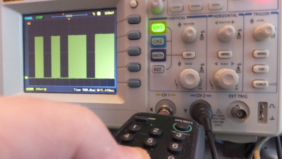
Silver Bullet - displaying marks and spaces of IR signal on oscilloscope (1Volt peak, 200mV/500uSecs per division)
To construct this device, the pins of the IR LED are soldered to the connector with the cathode (-) being connected to negative and the anode (+) being connected to the positive terminal. To get cleaner falls on the signal solder a 22K ohm resistor across the legs of the IR Led. The resistor value isn’t critical as we tried several values down to 7K ohms and didn’t notice any appreciable difference in signal quality. We were pleasantly surprised at the fidelity of the signal, as long as you hold your remote control steady and in position.
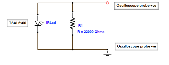
Silver Bullet Infrared Receiver circuit diagram
In our tests we were consistently able to display & trigger signals on the screen of the oscilloscope with 1 volt peaks, with ease. Another benefit of this approach is that there is no additional noise creeping in from external power supplies.
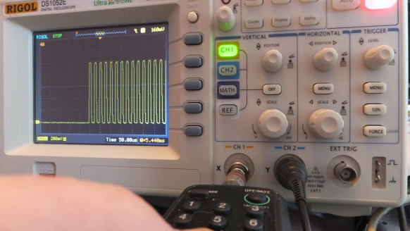 Get accurate measurement of modulation frequency & duty cycle.
To make it easy to construct and use over an extended period with the Oscilloscope we used a 2 part connector. The first part is a standard male BNC to female RCA adapter and the second part which houses the IR LED is a special male RCA connector plug with plenty of room to mount the IR LED.
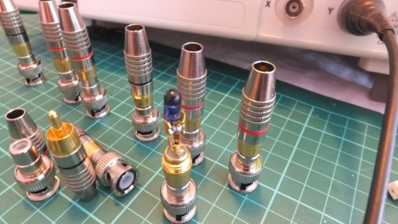 An Inside View – showing the IR Led, BNC & RCA connectors.
DIY Instructions
STEP1: If you have a diode checker on your multimeter, check that the LED is working. For the TSAL6100 our multimeter shows 1.48V for forward voltage.
STEP 2: Solder the 0805 SMD 22k ohm resistor across the legs of the IR LED, near the top (Bulb). Now confirm the resistance across the legs of IR LED is 22K, using your multimeter. Check that the IR LED is still working as in step 1.
STEP 3: Cut the bottom of the legs off the IR LED so that when it is all assembled the LED bulb will be completely within the RCA plug. You can leave it longer and outside the plug if you wish, but we think it’s neater if it’s all inside. Keeping it just inside the RCA plug makes it much easier to align with the remote control.
STEP 4: With the RCA cover off, solder the legs of the IR LED to the RCA plug. The anode goes to the central connection (signal) and the cathode goes to the outer part of the RCA plug (negative/shielding). We were going to use heat shrink tubing to insulate the legs of the IR Led, but in the end it wasn’t needed. Depending on your setup you may require it. We will consider adding a bit of hot-glue later, if needed, which will provide extra stability and insulation.
STEP 5: Now place the cover onto the RCA plug and insert the RCA plug into the BNC adapter. You are now ready to connect your receiver to the Oscilloscope.
By far the trickiest part of this assembly, was getting the SMD 0805 resistor soldered to the legs of the IR LED. Next time we will solder it on beforehand rather than after the LED is cut and soldered to the connector.
Parts list:
Uses
The reason we needed a receiver like this, is related to our post on Infrared signal lag & distortion with IR Receivers. We need to be able to validate the quality of IR signal transmission and reception for a new product we are finishing off at present. The ‘silver bullet’ receiver gives us yet another source of validation to satisfy our requirements.
A more common use for a device like this would be to validate if your standard IR receiver is working correctly with difficult signals you are trying to decode. Frequently, we are asked by ‘Makers’ trying to decode difficult signals for assistance and this little device would quickly verify if the problem is with the IR receiver. Often, for longer Air Conditioner signals the basic or cheaper IR receiver isn’t able to cope.
This device will also allow you to measure the modulation frequency of any IR signal, using your Oscilloscope.
Of course you can also mock up this circuit on a solder-less breadboard quite easily, but we prefer to have a convenient device that we can just leave plugged into the spare channel of our oscilloscope.
By all means make your own version of this receiver or if you prefer - order these parts or a pre-assembled unit by adding to your cart above. Also check out our other products available on our Tindie Store or via our own website
TIP
Set the timebase of your oscilloscope from 10->50 uSecs to measure Carrier Frequency and set the time base from 2->10 MSecs to capture the full signal. Set the Volts/div to 200 mVolts for best results, as the peak voltage achieved can be from 1->1.2 Volts. We sometimes attach the sensor to the end of a coax cable with BNC connectors, which allows us to move it around the bench, if the scope is up on a shelf. Always remember to set the probe to 'x1' for the IR channel.
The Maker
The Silver Bullet will be assembled and shipped by our Summer Intern. After allowing for costs such as parts, shipping, Taxes & Tindie fees etc, all proceeds will go to the intern.
No country selected, please select your country to see shipping options.
No rates are available for shipping to .
Enter your email address if you'd like to be notified when Silver bullet – Oscilloscope Infrared Receiver(IR) can be shipped to you:
Thanks! We'll let you know when the seller adds shipping rates for your country.
| Shipping Rate | Tracked | Ships From | First Item | Additional Items |
|---|---|---|---|---|
|
:
|
Buy with confidence.
Our Tindie Guarantee protects your purchase from fraud. Learn More
Dublin, County Dublin, Ireland
Ships from Ireland.
19 Reviews | 439 Orders
$29.99
Free Shipping!
$15.00
Free Shipping!
$10.00
Free Shipping!
$15.00
Free Shipping!
$20.00
Free Shipping!
$40.00
Free Shipping!
$12.00
Free Shipping!
$15.00
Free Shipping!
$6.18 $8.59
Free Shipping!
$7.99
Free Shipping!
$55.00
Free Shipping!
$1.05
Free Shipping!
By clicking Register, you confirm that you accept our Terms & Conditions
We recognize our top users by making them a Tindarian. Tindarians have access to secret & unreleased features.
We look for the most active & best members of the Tindie community, and invite them to join. There isn't a selection process or form to fill out. The only way to become a Tindarian is by being a nice & active member of the Tindie community!
