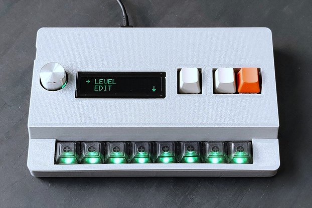
Control a synthesizer using 5 control voltages, 2 gates, and an LFO mapped to a Nunchuk Controller.
Designed by Sonoclast in United States of AmericaThis product is no longer available for sale.
The seller may be offering an improved version or it may be hanging out on the beach, enjoying the retired life.
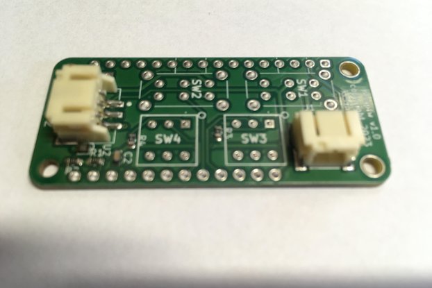
This began as an experiment with a Nunchuk Controller as an unconventional interface for musical expression. I created a pair of these as part of my entry to the 2018 Moog Circuit Bending Challenge.…
Read More…This began as an experiment with a Nunchuk Controller as an unconventional interface for musical expression. I created a pair of these as part of my entry to the 2018 Moog Circuit Bending Challenge. After using the pair to control a drum machine I wanted to make some more to interface with other synthesizers, and I wanted a proper PCB so that the Nunchuk Controller could be attached using the existing plug.
A few notes and specifications:
You will need to provide your own official Nintendo (white) Nunchuk Controller. From what I've read, non-white and/or non-official controllers use different startup sequences, and my code only accounts for the official white controllers. I got mine shipped for less than $10 at amazon.com.
The board is powered by a GND line and a +5V line. The pads are clearly labeled on the left side of the board. It can be powered from any typical clean +5V synth power connection, like a Eurorack power supply or a +5V line from a Moog Werkstatt circuit board. I've personally had bad results (didn't fry the board, but it didn't work) with trying to power it from a USB port due to how noisy USB power is.
The Nunchuck connector is plugged on the top of the board with the notched side up. The fit is snug, so take care to ease it into place. It is not intended to be hot-plugged (unplugged or plugged while powered). It probably would not hurt anything, but it probably wouldn't work either.
The eight outputs are clearly labeled and connected to a female pin header along the bottom of the board. The five control voltages range from 0-5V and are mapped to joystick X (SX), joystick Y (SY), accelerometer X (AX), accelerometer Y (AY), and accelerometer Z (AZ). The 2 gates, 0V OFF and 5V ON, are mapped to the C (BC) and Z (BZ) buttons. The SAW connection is a software and digital approximation of a sawtooth LFO. Watch the end of the demo video to see how it performs. The LFO frequency is controlled by the accelerometer's Y-axis (forward and backward), and the LFO can be retriggered with the C button. (The accelerometer Y control voltage and C button gate are usable independently or in conjunction with the LFO.)
By clicking Register, you confirm that you accept our Terms & Conditions
We recognize our top users by making them a Tindarian. Tindarians have access to secret & unreleased features.
We look for the most active & best members of the Tindie community, and invite them to join. There isn't a selection process or form to fill out. The only way to become a Tindarian is by being a nice & active member of the Tindie community!